This use case demos the power of graphic schematic mode vs text mode in netlist debugging. Verilog netlist has long and hard to read strings. When converting to schematic, it's much easier to understand the connectivities.
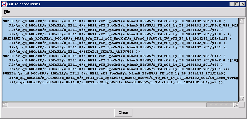
There are four gates in instance 'PgM' having connections as the following text window showed. It's very difficult to figure the real connections between them.

Figure 1. Four gates have long net strings in connections
It's hard to figure out the connections relationship between them by reading the text file. If display them in schematic mode, it would be very easy to show if they are connected together
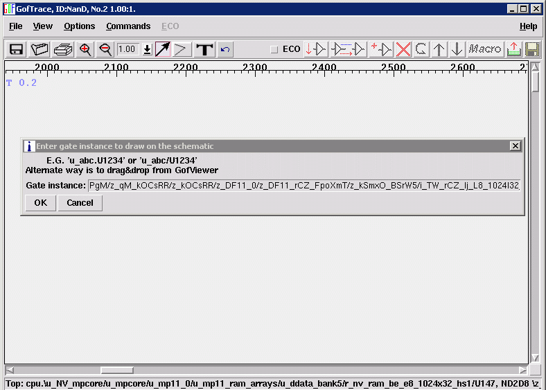
Use GOF load_gate feature, by copy and paste one of the gate instance, click OK button.

Figure 2. Load one instance
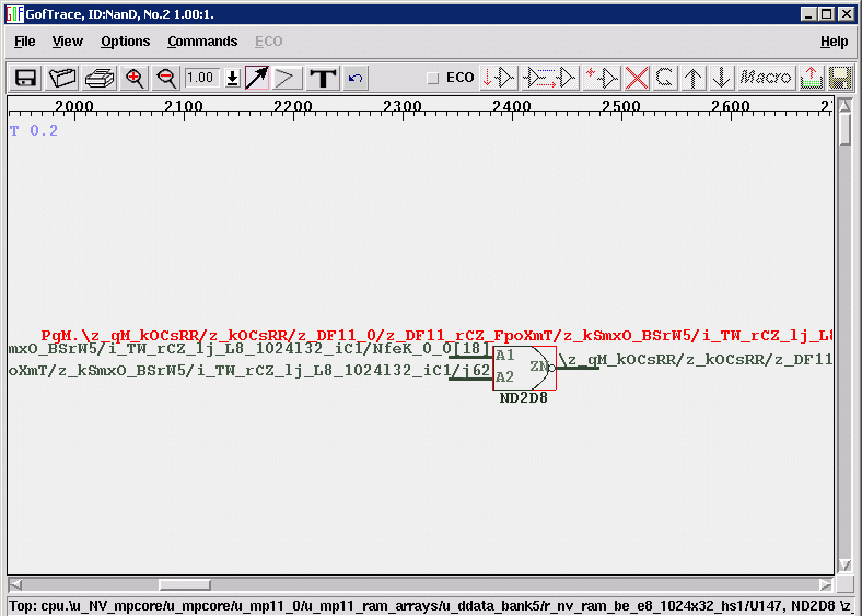
The instance is drawn on the schematic, click on the input pins and output pin of the gate.

Figure 3. The instance is loaded
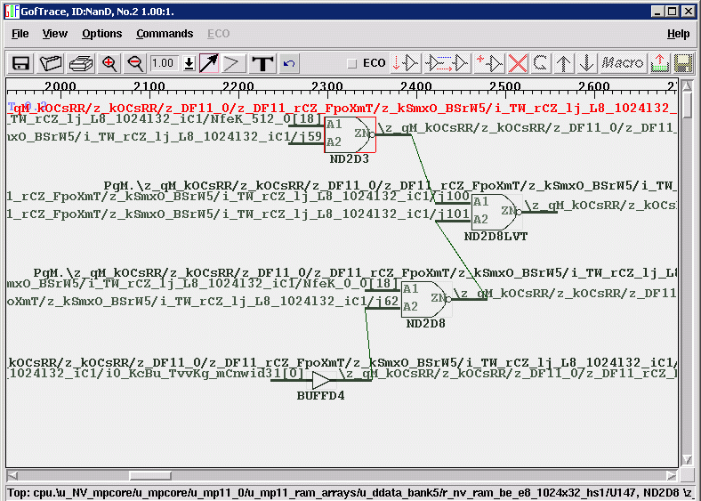
Use mouse-middle-button click on the gate input/output pins.

Figure 4. Schematic is created
A partial meaningful schematic was created by simple mouse clicks. It is much more intuitive than text mode.