Adaptive Retiming refers to an advanced timing optimization technique in which registers and latches are moved forward or backward within combinational logic to optimize the worst negative slack (WNS).
As shown in Figure 1, when the combinational logic before and after a register is either too tight or too loose, the register is moved towards the tighter side. This operation redistributes some of the tight logic to the looser side, making the logic delays more balanced. While moving the register, logic equivalence is maintained by automatically duplicating or merging as needed.
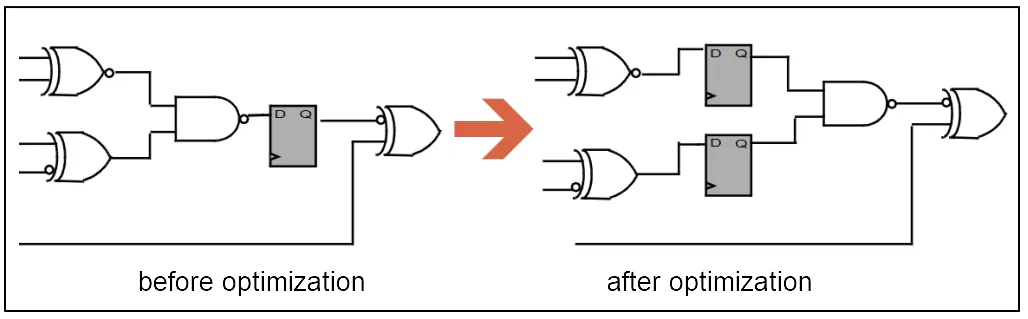
Figure 1: Before and after retiming
For the data path at the D input of a register, this data path has M inputs and one output. If this data path becomes a timing bottleneck and requires retiming and splitting, suppose we divide it into two parts, A and B, with the intention of moving B to the right side of the register for delay optimization. Logic B has N inputs and one output, so after retiming, N registers need to be duplicated to the left side of B.
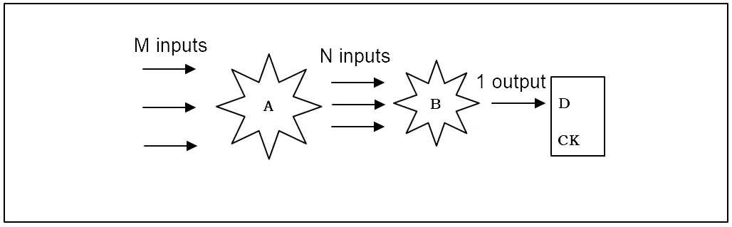
Figure 2: Duplicate flops in retiming
Therefore, splitting logic to the right causes register duplication, significantly increasing the number of registers. Conversely, if part A is moved one level to the left, the registers will be merged and reduced.
From another perspective, for a sub-module, if Adaptive Retiming is only performed internally, the module's input and output functions remain unchanged. In other words, if registers are moved by a few clock cycles forward or backward, the overall logic remains the same after the move, as shown in Figure 3.
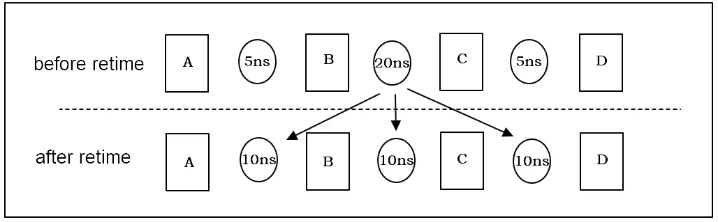
Figure 3: No function change after retiming
During Logical Equivalence Checking (LEC), since the combinational logic has been split, the logic between registers B and C before and after retiming will inevitably differ. However, from the perspective of the overall path from register A to D, the logic is still equivalent. Therefore, B and C can be ignored, and only A and D should be considered as key points. The segment from the Q output of register A to the D input of register D is treated as a single unit for checking. Unlike a typical logic cone, this unit contains two stages of registers. When stimuli are applied to this unit, it takes two clock cycles to see the results at the D input of register D. This type of LEC, which considers clock cycles, is called Sequential LEC.
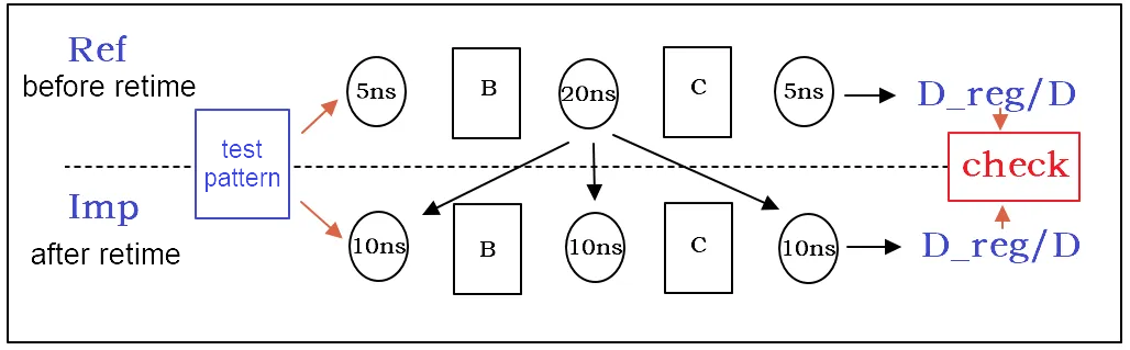
Figure 4: Sequential LEC
In practice, for RTL-to-gate LEC, an SVF file can indicate whether a netlist has undergone retiming optimization and detail how the retiming was executed. In gate-to-gate LEC, if one gate-level netlist is original without retiming while the other has retiming applied, the modules with retiming can be set as blackboxes. Sequential LEC checks can then be performed separately on the retimed modules. GOF Formal is capable of performing the sequential equivalence checking.