The mixed functional ECO flow combines both automatic and manual modes seamlessly to improve the efficiency and quality of functional ECO operations. GOF ECO integrates these two modes, allowing users to perform all ECO-related tasks in one environment without switching between different scripts or netlist files for preprocessing and post-processing. This unification saves time and reduces errors while enabling more control over the changes made to the design.

Figure 1: Seamlessly Integrated Manual and Automatic ECO
The following use case shows how to use GOF to do ECO by mixing Automatic Mode and Manual Mode. When Manual ECO is possible, it normally gives better solution than Automatic Mode. Pure manual work done on netlist text file directly is tedious and error-prone. GOF supports GUI Mode and Script Mode to improve efficiency and accuracy of Manual ECO. In Script Mode, GOF has rich API sets to boost performance of Manual Mode ECO. In this ECO, hundreds gates have been saved by mixing Automatic and Manual ECO.
The netlist under ECO has one input bus port driving two combinational logic clouds (LOGIC A and LOGIC B) which may have overlap and drive two sets of flops STATE_A_reg and STATE_B_reg respectively.
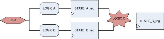
Figure 2: The netlist under ECO has one input bus port drives two types of flops
The ECO requires a new input port IN_B being added to drive 'LOGIC B' and flop STATE_B_reg. And other flop STATE_C_reg has modifications as well which will be done by Automatic Mode.
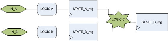
Figure 3: The ECO requires to separate the two paths by a new port
The input bus port has width of 96 bits, when Automatic Mode ECO applies on the whole module, total ~120 new gates are needed in IN_A/IN_B separation. These new gates can be absorbed in full layer ECO. However in metal only ECO, it maybe impossible to find enough resources for these new gates.
# Automatic mode only
use strict;
undo_eco;  Discard previous ECO operations
# Setup ECO name, had better be unique to avoid naming confliction
setup_eco("eco_example");
read_library("art.5nm.lib"); # Read in standard library
read_svf("-ref", "reference.svf.txt");       # Optional, must be loaded before read_design, must be in text format
read_svf("-imp", "implementation.svf.txt");  # Optional, must be loaded before read_design, must be in text format
read_design("-ref", "reference.gv");  # Read in the Reference Netlist
read_design("-imp", "implementation.gv");  # Read in the implementation Netlist Which is under ECO
fix_design;
We will see that lots of gates can be saved by mixed mode
A basic analysis on port IN_A shows, the port has two sets of fanouts, one is for "LOGIC A", the other is for "LOGIC B". If we can separate out the fanout for "LOGIC B" and reconnect the driver to port IN_B, the ECO in this spot would be done without any new gate added. Or if there are few gates shared by "LOGIC A" and "LOGIC B", duplicate these gates and drive them separately. GOF has APIs to do this type of Manual ECO.
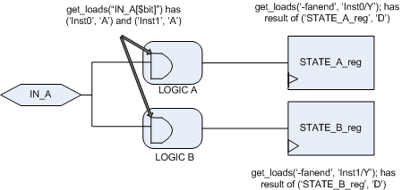
Figure 4: Fanout analysis
The ECO has two steps; The step 1 uses Manual Mode, and the step 2 uses Automatic Mode.
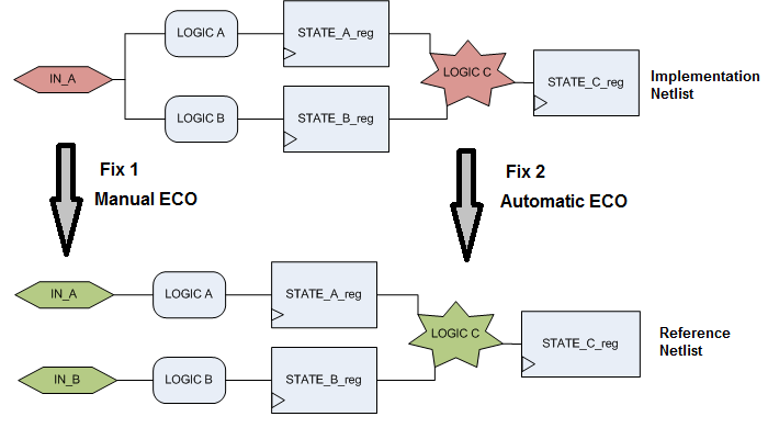
Figure 5: Mixed ECO
The step 1 script does the manual ECO:
# Mixed Automatic Mode and Manual Mode
# Any new gates added will be mapped to spare gates
use strict;
undo_eco;  # Discard previous ECO operations
# Setup ECO name, had better be unique to avoid naming confliction
setup_eco("mixed_mode_eco_example");
read_library("art.5nm.lib"); # Read in standard library
read_svf("-ref", "reference.svf.txt");       # Optional, must be loaded before read_design, must be in text format
read_svf("-imp", "implementation.svf.txt");  # Optional, must be loaded before read_design, must be in text format
read_design("-ref", "reference.gv");  # Read in the Reference Netlist
read_design("-imp", "implementation.gv");  # Read in the implementation Netlist Which is under ECO
# Fix the modified modules
# Do Manual ECO first. For loop to separate IN_A and IN_B
set_top("state_control");
for(my $bit=0;$bit<96;$bit++){
  # Work on each 'IN_A' bit, get the loads of IN_A individual bit
  new_port("IN_B[$bit]");
  my @loads = get_loads("IN_A[$bit]"); # The result has Inst0 and Inst1 shown in figure 3
  foreach my $load (@loads){
    # The load is in (inst, pin) format for each load
    my ($inst, $pin) = @$load;
    my @out_pins = get_pins("-output", $inst);
    my @fanout_flops;
    foreach my $opin (@out_pins){
      my $out_net = get_net_of($opin);
      if($out_net){
        my @flop_endpoints = get_loads("-fanend", $out_net);
        push @fanout_flops, @flop_endpoits;
      }
    }
    my @flop_insts;
    # Only need flop instance names
    push @flop_insts, $_->[0] foreach @flop_endpoints;
    if(grep($_ =~ m/STATE_B_reg/, @flop_insts)){
      change_pin("$inst/$pin", "IN_B[$bit]");
    }
  }
}
The step 2 is to do do Automatic ECO
# Auto ECO is done by fix_design command
fix_design;
# Save final result
report_eco();   # ECO report
write_verilog("eco_verilog.v"); # Write out ECO result in Verilog
In this example, by utilizing the mixed mode, the number of newly introduced gates was reduced from 120 (in automatic-only mode) to 15, all of which were necessary for modifications to LOGIC C. The manual optimization of the netlist before automatic ECO saved resources, especially valuable in metal-only ECO situations.
Mixing manual and automatic ECO modes can significantly improve the efficiency and quality of ECO processes. The manual mode provides greater control, enabling the optimization of resources, while the automatic mode accelerates the handling of standard changes. This approach is particularly beneficial in scenarios with limited resources, such as metal-only ECOs, where minimizing the addition of new gates is critical.