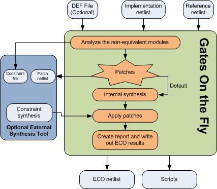
In Metal Only ECO, the design has completed place and route. Any new gates added should map to spare gates that located in the design. GOF supports Standard Spare Cells and Metal Configurable Gate Array Spare Cells post-mask metal only ECO.

Figure 1: Metal Only ECO
In metal only ECO, the primary objective is to fix the logic without altering the base layers, thus avoiding costly and time-consuming changes to the silicon. The process involves two main steps: fixing the logic and mapping new gates to spare type gates. This article focuses on the second step, detailing how spare gates are utilized in metal only ECO and the intricacies involved in standard cells spare gates mapping.
1. Fix Logic Automatically: The initial step is to automatically correct the logic in the design. This involves identifying the required changes and determining how these changes impact the existing netlist.
2. Map New Gates to Spare Type Gates: The subsequent step is to map all new gates to the existing spare gates. This requires a specialized synthesis process to create a new netlist patch that exclusively uses gate types available in the spare gate list. Special attention is needed for flip-flop (flop) mapping to ensure compatibility.
GOF ECO employs an internal synthesis engine to map the patch logic onto spare gates. The spare gates should comprise specific combinations to ensure optimal area and performance. The primary combinations are:
Among these, the second combination (two ports 'nand/nor' gates, 'inv' gates, and flops) offers the least area, while the third combination (two ports 'nand/nor/and/or' gates, 'inv' gates, and flops) provides the best performance in metal only ECO scenarios.
In the mapping process, as illustrated in Figure 2, gates such as MUX and flops are mapped directly onto the spare gates due to their one-to-one correspondence with the spare gate list. However, more complex cell types like AO32 require synthesis and mapping onto multiple simpler gates. For example, an AO32 gate might be synthesized and mapped onto three AND gates and one NOR gate.

Figure 2: Standard Cells Spare Gates Mapping
A common challenge in metal only ECO is when the new flop required has a different set/reset type compared to the available spare flops. For instance, an ECO may necessitate a set-type flop, but the spare flop list might only provide a reset-type flop. In such cases, GOF ECO uses a phase invert technique to map the set flop to the available reset spare flop, ensuring functionality is preserved.

Figure 3: Map new set-type flop to spare reset-type flop in metal only ECO
Metal only ECO is a critical process in ensuring the efficient and cost-effective implementation of design changes. By leveraging spare gates and utilizing specialized synthesis techniques, it is possible to map new logic onto existing spare gates, thereby avoiding the need for more extensive silicon modifications. Understanding the combinations of spare gates and the mapping process is essential for optimizing area and performance in metal only ECO.
GOF ECO utilizes a heuristic method that employs constraints to identify the optimal mapping of spare gates. The process involves setting constraints to restrict the types of NAND/NOR/AND/OR gates to be considered, and then conducting a mapping exercise to identify the nearest available spare gates. The cost of the mapping is determined by adding the distance between the measured location and the actual location of the spare gate. For example, if a NAND gate needs to be mapped in a metal only ECO, and the measured location is (100, 100), while the closest spare gate (spare_0) is located at (120, 120), then the cost is calculated as (120-100)+(120-100)=40. The method involves multiple iterations, and the optimal solution is selected based on the lowest cost.
To ensure that new instances are accurately mapped to the nearest spare gate instances, it is necessary to have a Design Exchange Format (DEF) file. Without loading the DEF file, the GOF process will use spare gate types without precise mapping to exact spare instances. However, P&R tools like SOC Encounter will map new instances in the new netlist to the closest spare gates.
During the 'fix_design' command, GOF examines the top-level module and its sub-modules to identify any non-equivalent points and optimize the logic cone to create a patch circuit with the minimum number of gates.
Spare gates are incorporated into the design and their percentage relative to the entire digital area is usually dependent on the design maturity. For instance, the first version of a design typically requires a higher percentage of spare cells, usually around 8-10% of the entire digital area. As the design progresses to the second version, a lower percentage of spare cells, approximately 4-5% of the total digital area, is sufficient. By the third version, less than 3% additional spare cells may be necessary. Additionally, during the backend placement process, any remaining empty space can be filled with extra spare gates.
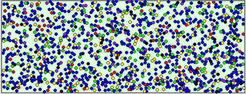
Besides the spare gate area percentage, the proportion of various spare gate types is also crucial. For example, a design with 126K instances may have spare gates in different categories, as depicted in the following figure:

Figure 4: Spare Gates numbers and distribution
Usually, spare gates are uniformly distributed on the floor plan, as shown in figure 4. Nevertheless, if accessible, users can adjust the distribution based on historical metal only ECO data. Blocks that are prone to design changes may require more spare gates, while mature logic may require fewer spare gates.
Check Standard Cells Metal Only ECO for detail